Making a laptop stand
When the latch disappeared from an ancient wrought iron front gate, I asked a metalwork company to look at the gate and make a replacement latch. A lever latch is about as simple a device as can be imagined. Knowing where it needs to fit, how could anyone get it wrong? Yet the first replacement didn't work: with a decorative curling handle, the centre of gravity was marginally on the wrong side of the fulcrum, causing the latch to rest in the open position.
An obvious mistake, you think? Then here's a test: without looking at one, try to draw a diagram of a can opener in sufficient detail for someone to physically reproduce it.
If you found that more difficult than you expected, then you're not alone. When tested on their understanding of everyday devices such as zippers, participants in controlled experiments are consistently surprised to discover that their mental models are like the facade on the set of an old Western: open the saloon door and there's only desert behind. In cognitive psychology, this phenomenon is known as the illusion of explanatory depth (more on that below).
Because our knowledge of the physical world is much shallower than we think, designing and constructing something even as simple as a laptop stand can be an interesting exercise.
It will be clear that I'm not a carpenter, but if building with wood appeals to you more than casting some plasticky thing with a 3D printer then the stand design here might be something you can adapt or improve. Of course, that will be only at your own risk.
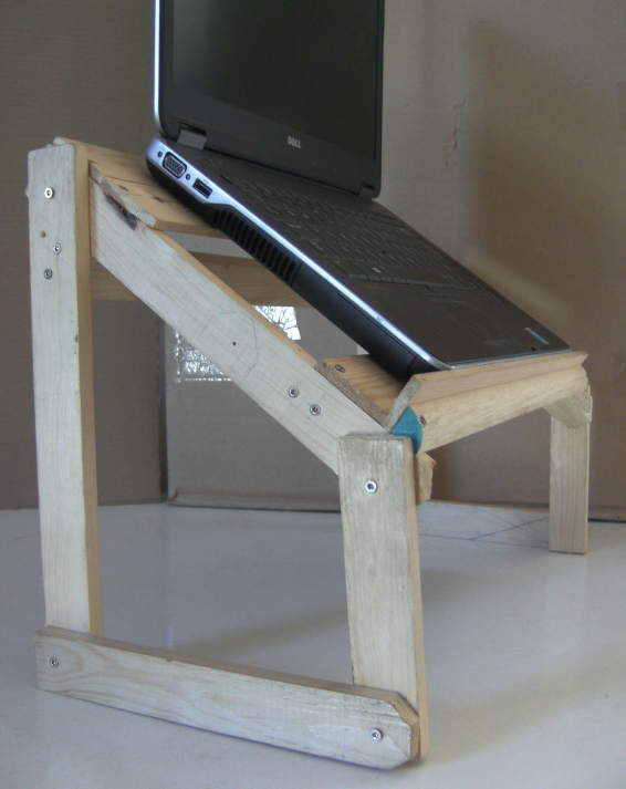
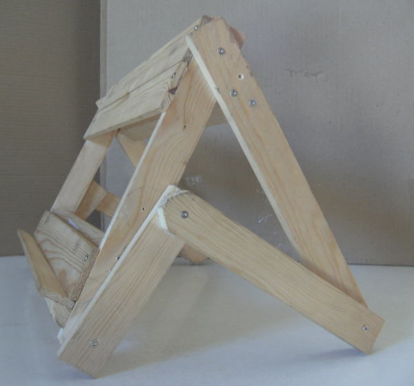
I say "design", but it was developed according to an Agile Methodology, so pretend that I've lost my blueprints and go by the pictures. Above, the stand is seen standing, but it is adjustable, so it can also kneel or crouch:
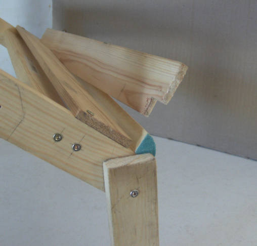
The shelf that supports the laptop (or book, or painting-in-progress if the stand is used as a desk easel) fits in a gap at the bottom of the tray, so it can be pulled out and replaced with a deeper or shallower one. Also, the size of the quad moulding can be chosen so that it will support an ultra-thin laptop without any shelf being present.
Materials
Wood, in three cross sections: 6mm x 44mm for the tray's slats and shelf, 16mm quad moulding for the bottom of the tray (the end of which is blue in the picture above), and 12mm x 34mm for the rest.
Wood screws (24). In length, at least 16 screws need to be about double the thickness of the thicker pieces, or a bit less. I used 25mm screws, 1mm over that 2 x 12mm limit, but the screw heads are not flush with the wood (to use the jargon of the trade, I didn't "countersink", except for the two screws fixing the quad moulding to the tray) so, despite being marginally too long, the points do not protrude.
Drill to make pilot holes for the screws.
Ideally, a mitre saw. There's no need for a fancy electric one, a hand-held one is fine, with a box or something to hold the wood steady while you saw it. I couldn't find the mitre saw I used to have, so I settled for an ordinary saw, making the result a bit rough.
Piece lengths
For me, the wood above came in 2.4m lengths. How many you need will depend on wastage, as well as on whether you decide to alter the tray width or other dimensions.
Legs: front 2 x 155mm and back 2 x 305mm.
Stretchers (connecting the legs): 2 x 225mm (but see below).
Tray sides: 2 x 290mm.
The last two pieces of thicker wood are the two cross beams, one between the sides of the tray, and one between the two back legs. I made the tray 430mm wide, so the two crossbeams are 406mm (= 430 - 2 * 12) and 430mm, respectively.
Tray slats and shelf: 4 x 430mm. Or 5 for two swappable shelves for different load depths. More slats are possible, but unnecessary: the gap is good for a laptop's fan.
Quad moulding: same length as slats.
Stability
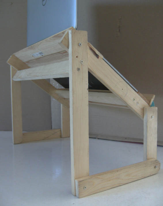
In the elevated position, the tray cannot roll backwards, i.e., it cannot close the angle it makes with the back legs. That's because the base of the tray is hard against the crossbeam between the back legs. For a view of that crossbeam, see the picture at the top of this page showing the back of the stand.
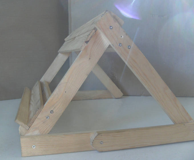
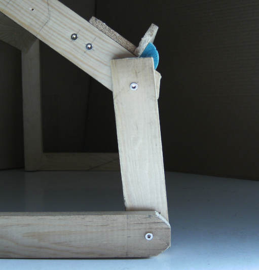
But what stops it rolling forwards? Notice in the picture below that the front legs are not quite vertical, but instead lean back a little. The downward pressure of the load holds them that side of vertical unless the tray is deliberately pulled forward to collapse the stand to the lowered position.
One way to ensure you get this right is to do things in this order: fit all the legs to the tray, then fix the crossbeam so that the back legs are vertical when the tray is against it, then finally cut the stretchers at a length that will make the front legs lean back slightly.
(You will see that I rounded some corners. Without a mitre saw, I decided not to do any more.)
Articulation
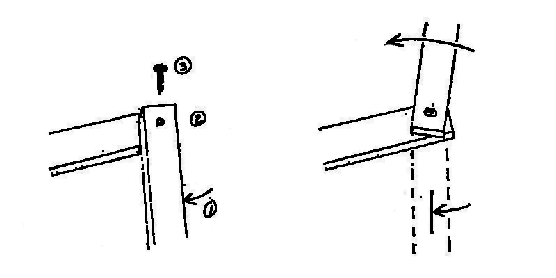
You might have guessed that what makes the stand adjustable is the fact that the screws which fix the legs to the side of the tray are rotating with the legs, and the same is true of the screws fixing the stretchers to the legs. I knew that this could work because I previously did it when making a collapsible saw horse from some waste lumber. I have never seen it done anywhere else, so it might be unorthodox, but it works.
The trick is to screw the pieces together in the position where the upper piece is at its maximum required clockwise rotation relative to the lower piece. It is then possible to rotate the upper piece anticlockwise (opening a tiny gap between the two pieces) and back clockwise (until the gap closes again). The easy way to remember this is to think of the upper piece as becoming part of the screw: screws go in clockwise and come out anticlockwise.
It can be convenient to drill the pilot holes with the two pieces held together in a different relative rotation, and only after that to rotate the upper piece to its maximum required clockwise position, align the holes again, and put in the screw.
Tray
The crossbeam in the tray adds some rigidity to the tray, though it might not really be needed. It's near the bottom of the tray only because it served a dual purpose in an earlier iteration.
To assemble the tray, I first screwed the top slat and quad moulding to the tray sides, ensuring the sides were straight. Then I allowed the shelf to rest against the quad moulding and fitted the bottom slat against the shelf before fixing the slat in position with two screws - making the shelf snug, but not so tight that it could not be pulled out.
Choices
Most people will prefer a design with an adjustable tray angle and will not care about the possibility of elevating the tray. In fact, using lockable joints, it would be possible to have both these features. I had to take care to get a tray angle and elevation I would be happy with. In the collapsed position, however, either the base takes more desk space than I would like or, if folded tighter, the angle of the tray is a bit steeper than I might wish. For me, that's not a problem, as I already have a metal stand for that use case.
Notes
The term "illusion of explanatory depth" (IOED) comes from a 2002 paper by Leonid Rozenblit and Frank Keil published in the journal Cognitive Science. It is a metacognitive failure particular to devices (such as sewing machines and flush toilets) and to natural phenomena (such as tides and rainbows) as distinct from facts or procedures, which were the subject of controlling experiments. The authors conjecture that the IOED may be an adaptation that avoids "potentially inexhaustible searches for ever-deeper understanding by satiating the drive for more knowledge once some skeletal level of causal comprehension is reached."
For a non-academic article on our unconsciously superficial knowledge of both built artifacts and the physical world (also using the example of carpentry, as well as Haskell, and even boiling water), read John Salvatier's Reality has a surprising amount of detail.
